Catalytic reactor engineering ⇒ information-driven design of packed (operando), fluidized, multi-functional, and -phase reactors

Problem statement

At lab-scale, the ultimate goal of a catalytic reactor is to provide (1) reliable kinetic information, neglecting or controlling other phenomena (heat-mass transfer and hydrodynamics); (2) high-throughput data to amplify the results, accelerate model and catalyst discoveries; and (3) results with the minimum requirements of reactants and wastes generated. The pillars of these reactors are quality, quantity, and safety.

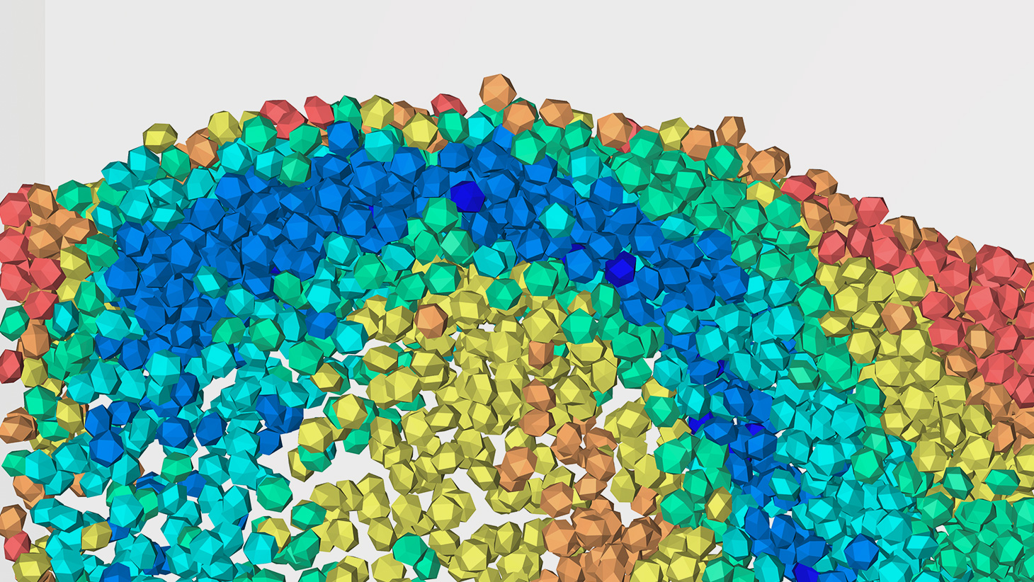
We design, build and test different laboratory-scale reactors. Our strategy involves creating and testing reactor prototypes while modeling these using our workflow. We have high-speed cameras, probes, and other measuring instruments to understand the reactor behavior. We focus on packed-, fluidized-bed, and multiphase reactors:

In packed bed reactors, we focus on forced dynamic and operando reactors. These are the quintessence of information-driven reactors where the dynamics can involve flow changes, temperature, pressure, partial pressure, presence of activity modifiers (poissons, H2O…). In operando reactors, we follow a spectro-kinetic-deactivation-hydrodynamic approach to resolve the individual steps involved. In fluidized bed reactors, we focus on downers and multifunctional reactors (circulating, multizone or two-zone, Berty reactors) We focus on trickle-bed, slurry, and bio-electrochemical reactors in multiphase bed reactors.

Al pilot-plant scale, we aim to reach the maximum productivity levels while solving the growing pains: the scale-up. Based on a robust kinetic model obtained in the intrinsic kinetic reactor (lab-scale) and using computational fluid dynamics, we design, build, and operate pilot plants. At this stage, we seek partnerships with investment or industrial enterprises to make these pilot plants.

Goals

  • Multifunctional fluidized bed reactors ⇒ multizone, circulating...
  • Packed bed membrane reactors
  • Forced dynamic reactors ⇒ pulsing, SSITKA...
  • Forced dynamic operando reactors ⇒ DRIFTS, TPSR...
  • Operando reactors
  • Spray fluidized bed reactors
  • Downer reactor I ⇒ micro downer
  • Downer reactor II ⇒ counter-current and scale-up
  • Batch Berty reactor ⇒ short contact time
  • Multiphase reactors ⇒ trickle bed and slurry
  • High throughput experimentation (HTE) reactors
  • Photo-thermal and bioreactors
  • Reactor visualization and prototyping lab
  • Spatio-temporal hydrodynamic characterization and validation

Related People

Related Covers

Related Publications

Coking and Sintering Progress of a Ni Supported Catalyst in the Steam Reforming of Biomass Pyrolysis Volatiles

by Ochoa, Arregi, Amutio, Gayubo, Olazar, Bilbao, Castaño
Appl. Catal. B: Environ. Year: 2018

Abstract

The valorization of biomass (pine wood) for hydrogen production has been studied in a two-step process, comprising pyrolysis and subsequent steam reforming of the volatiles produced in the first step. This work focuses on the deactivation of the Ni commercial catalyst used in the second step. Pyrolysis of biomass has been performed in a conical spouted bed reactor at 500 °C, and the in-line catalytic steam reforming of the pyrolysis volatiles, in a fluidized bed reactor at 600 °C. Deactivated catalyst samples were recovered at different values of time on stream, and analyzed by means of XRD, N2 adsorption-desorption, SEM and TEM microscopies, TPO, Raman and FTIR spectroscopies. The results show that the deactivation is mainly due to the encapsulation of Ni particles by coke, together with Ni sintering, to a lesser extent (from a Ni particle size of 25 nm in the reduced fresh catalyst, to 39 nm at 100 min). The former is ascribed to the condensation of oxygenates (particularly phenols), and the latter is inevitable within the current conditions. As the fraction of uncovered Ni particles decreases with time on stream, the deposition of encapsulating coke is slowed down (from a formation rate of 0.30 mgcoke gcatalyst−1 min−1 to 0.20 mgcoke gcatalyst−1 min−1, at 0–50 min and 50–100 min on stream, respectively), promoting the deposition of coke on the catalyst support (with a formation rate of 1.04 mgcoke gcatalyst−1 min−1 at 50–100 min on stream), with a more carbonized structure and formed through the thermal decomposition of phenols in the reaction medium.

Keywords

REF W2C ANW CRE